THERMODYNAMIC MODEL
THERMODYNAMIC MODEL
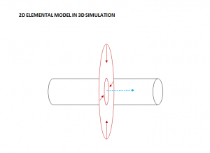
The thermodynamic model was performed through elemental simulation units.
It was developed in a partial 2D flow elements for the solution of the thermal flow equation.
The earth thermal flow is correlated in a dynamic system with the fluid flow inside the pipe
in order to establish a continuous energy stream in a solid/fluid thermal exchange.
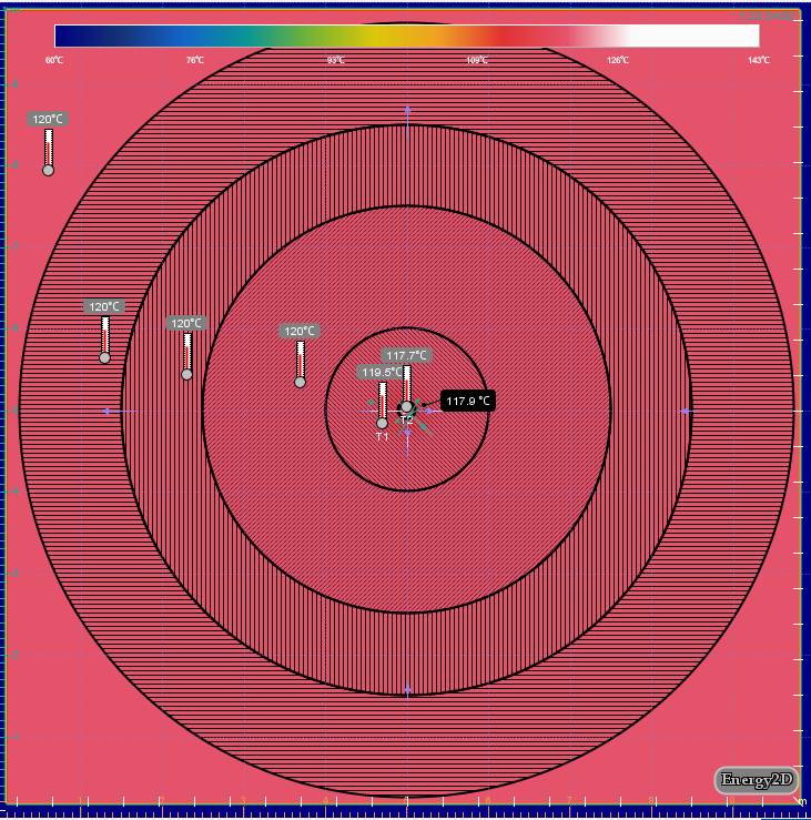
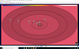
The feeding surface is simulated by 2D feeding disks perpendicular to the flow line.
The simulation have been finalized based on standard values of the thermal capacity and
conductivity of standard formations.
These parameters will be recalculated before each project based on 3D seismic measurements
and available well log measurements.
During the drilling project these parameters will be continually measured and updated in realtime.
NUMERICAL SIMULATION
Unit volumes used for simulation are conformed to the requirements
of electricity production power plants requiring a standard flow
rate of 100 Liter/Second and a temperature of 120° C to produce
about 3-4 MWatt electricity depending on the project system and
plant type, efficiency and manufacture.
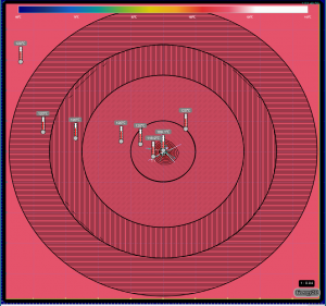
The calculation has been performed in a conservative manner accounting
for heterogeneity and anisotropy of thermal flow through formations
consisting of aggregates of different thermal conductivity and thermal
capacity mineral components and possible thermal barrier at the casing/
cement/formation interface.
The volumes account for the well geometry consisting of standard 7″
Liner. The flowing component has been discretized into units.
Each block unit have to absorb a total 30 * 10-6 Joules from the
formation during an equivalent circulation time.
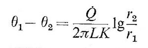
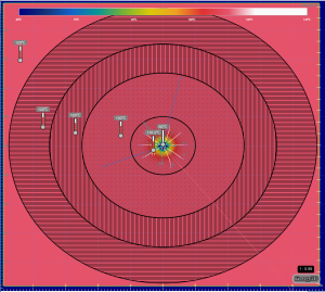
The total earth thermal flow Q has to equalize the flow rate of the fluid
through the casing and the lung volume and has to be compensated from the
earth thermal flow at the external near-field interface.
The thermal system is constrained by the thermal conductivity and capacity
of the formation aggregate and the flow component consequently adapted.
EFFICIENCY PARAMETERS PRODUCED BY THE SYSTEM (APPROXIMATED VALUES +/- 3%)
Flow unit:
~30 * 106 Joules (29.260.000 Joules)
Thermal rate:
~15 * 103 Joules/Sec (14.630 Joules/Sec)
Radial thermal conductivity of the 1st unit formation sector / area (average):
~105 Joules/Sec (102.885 Joules/Sec)
Radial thermal conductivity of the 1st unit formation sector / area (worst case):
~4.6 * 104 Joules/Sec (46298 Joules/Sec)
Recharge radial thermal capacity content on 2nd unit formation sector at 120°C (Vol) (average):
~105 Joules (105504 Joules)
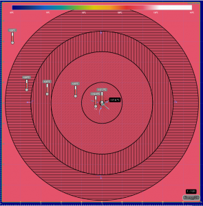
T Gradient perturbation @ external far field:
25-30%
Far field unit energy content:
~34 * 109 Joules (33.912.000.000 Joules)
Far field generating surface – volume energy content:
~27 * 1016 Joules
Worst case regeneration time:
3´ cycle.
Δt = 70°C
Simulation properties are intended for a standard pilot project based on realistic thermal formation parameters.
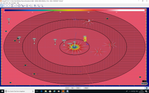
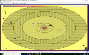
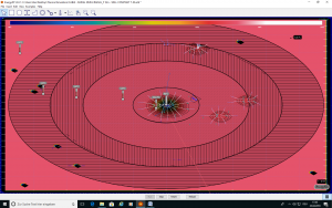
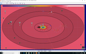

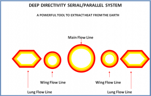
SCHEMATIC DDS_1 ELEMENTAL UNITS
Lung units allow to add over 30% additional efficiency to the main flow system.
DeepDirectivity Systems 1 – All Rights Reserved